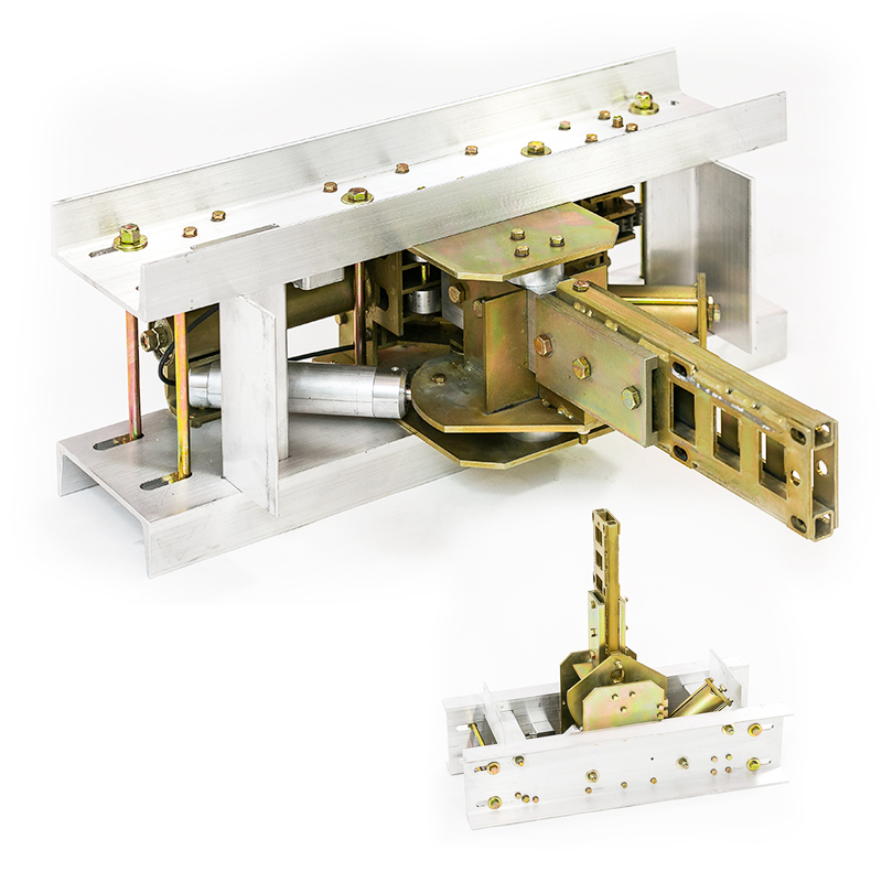
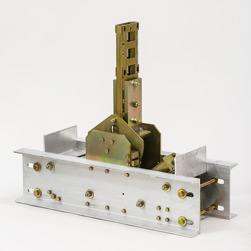
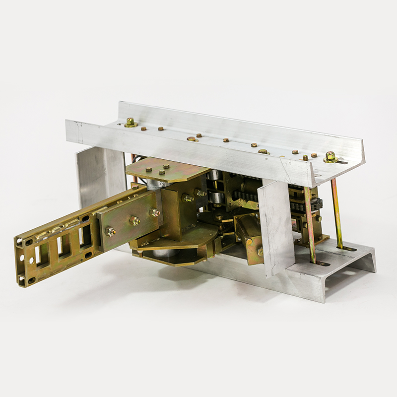
Description
Installation Instructions
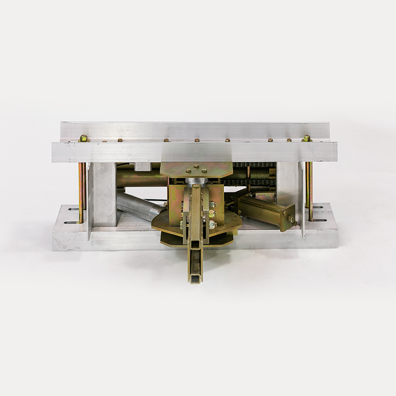
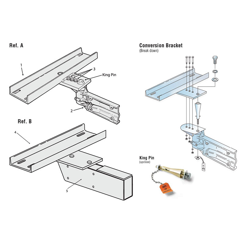
1.) Installation of the Unit is the same as any standard coversion bracket in the industry.
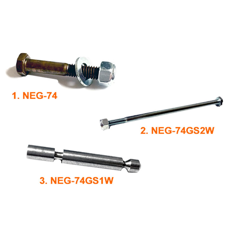
2.) The unit utilizes 8 Stainless Steel Bolts, which connect to the counterweight arms on both the top and bottom of the unit. The unit has slotted holes for possible variations from one Manufacturer’s design to the next.
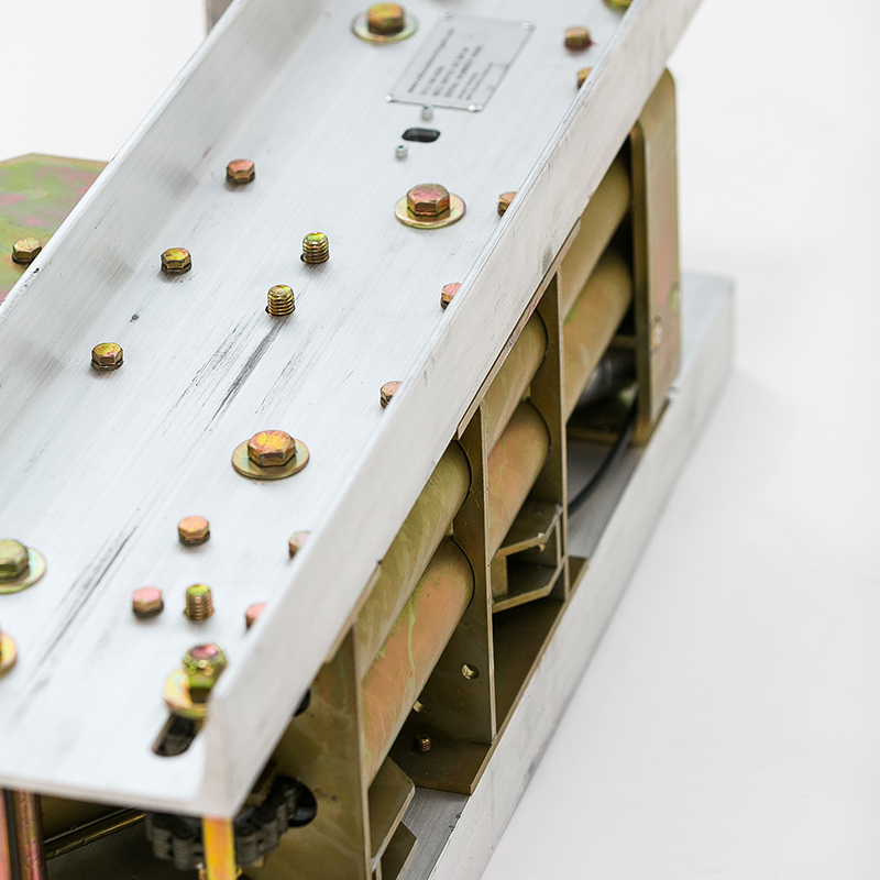
3.) The Unit is labeled “Right” and “Left” depending upon the particular crossing application. The “Right” on the top of the channel of the “Gate-Saver” should be used as the standard, which would be the entrance side of the crossing. Thus the Hydraulic would be on the track side of the unit, so as to allow the gate to swing into and up and away from the vehicle upon a collision.
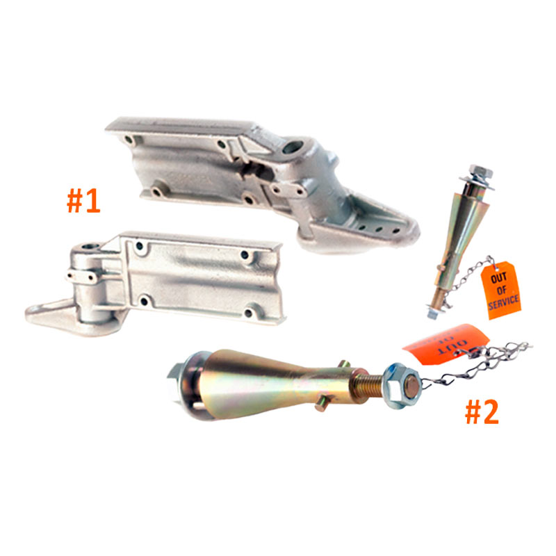
4.) The Unit labeled “Left” on the top of the channel would then be used in the exit or four quadrant gate crossing applications. Thus the Hydraulic will then face the field side.
5.) When maintaining the crossing for gate arm damaged parts, sections, lights or bulbs, detach the two bolts at the end of the hydraulic, which will then release the hydraulic from the cast sleeve, thus allowing the gate and sleeve to be moved without disconnect from the counter-weight arms to the side of the road. Thus putting your maintenance work out of the traffic lanes.

